STM32 CAN-BUS Reader
A revision of my very first PCB!
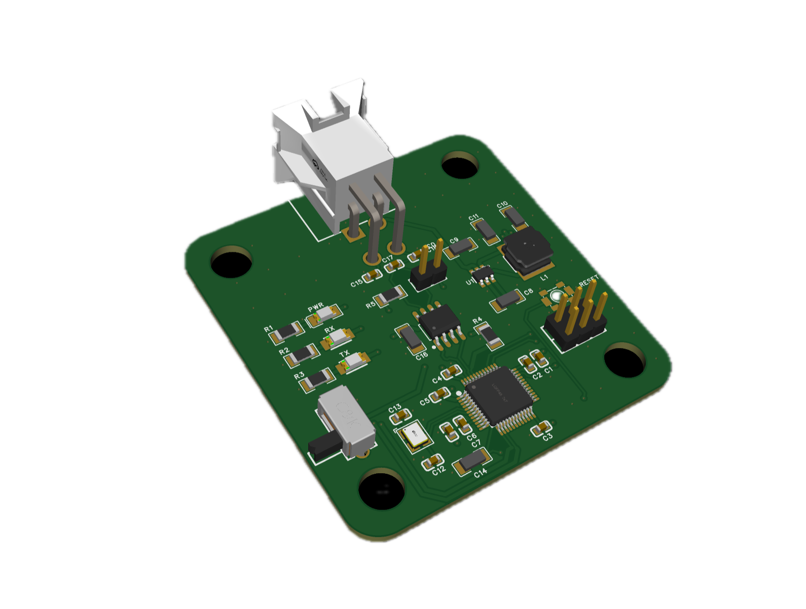
📌 Project Overview
This was one of my first boards that i designed. Also, the only project created using EasyEDA.
- Primary Goal: Communicate with a vehicles CAN-BUS, retrieve information. Configurable Baudrate.
- Tech Stack: EasyEDA, STM32F302, TCAN332. Designed & flashed on M1 Macbook using ST-Link V2.
- Status: Developed, ready to use.
🛠️ Key Specifications & Hardware Architecture
| Feature | Details / Components |
|---|---|
| Microcontroller | STM32F302C6T6 |
| Can Tranceiver | TCAN332DR CAN transceiver, compatible with ISO 11898 |
| Power | 12V Buck Converter System with Filtering |
| Intefaces | CAN-BUS, USB-C, SWD |
| Indicators | Power & CAN RX/TX LED’s |
| Stack-up | 4-layer board - Signal, GND, 3V3, Signal |
⚙️ Design & Implementation Details
I chose the STM32F302C6T6 as my MCU because it was available at my university and it had the GPIO and interfaces that I desired. It is relatively low-cost and it can handle monitoring the CAN-BUS without issues. I have also made a variant of this board which has a 0.96” OLED on it, for displaying CAN information.
I paired the MCU with an external crystal resonator for a more accurate clock. In my case, I used a 16MHz xtal.
The CAN circuit has a jumper on-board, which connects a 120Ω resistor to CAN-H line. This is necessary in most applications for matching cable impedance and it also helps out with swallowing signal reflections.
The power circuit uses a buck converter (AP63203), which has a fixed output of 3.3 volts. The input voltage range is rather wide, from 3.8V to 32V. This is something that I would change if I were to do this design again. Buck converters are essentialy switching regulators, they turn on and off rapidly. That rapid switching causes a lot of noise though. The automotive electronical enviornment is known to be noisy as is, so introducing an element with extra noise would be a no-go for me now, at least on this CAN-BUS board. Instead, I would opt for a linear regulator. Also - why on earth did I decide that routing the 3.3V out like that would be a good idea? I definetly knew about copper pours back then, no clue why I didn’t use one.
For debugging I used a ST-LINK v2, and in my design I implemented a basic SWD header. I even tried flashing this board with one of the cheaper Aliexpress ST programmers, and It worked like a charm. To toggle the bootloader state, I wired up a 3-pos switch to the STM’s BOOT0 pin, effectively being able to pull it HIGH or LOW (through a 10KΩ resistor, close to the MCU pin).
For extra swag I added three indicator LED’s. One of them was for power, the rest for CAN-BUS (TX/RX), driver by STM32 GPIO pin’s obviously.
Final thoughts and conclusion
There are a few tiny mistakes made with this board, from power supply design choices to mounting holes. There is a ton that I would re-do nowadays, but the board did work and was able to read out CAN-BUS on a 500Kbs baudrate.